Push Back robot, V5RC 2025-26
Our robot went to the VEX World Championship for Southern California, finished in the top 8% of teams there, and ranked #33 in the world in programming skills.
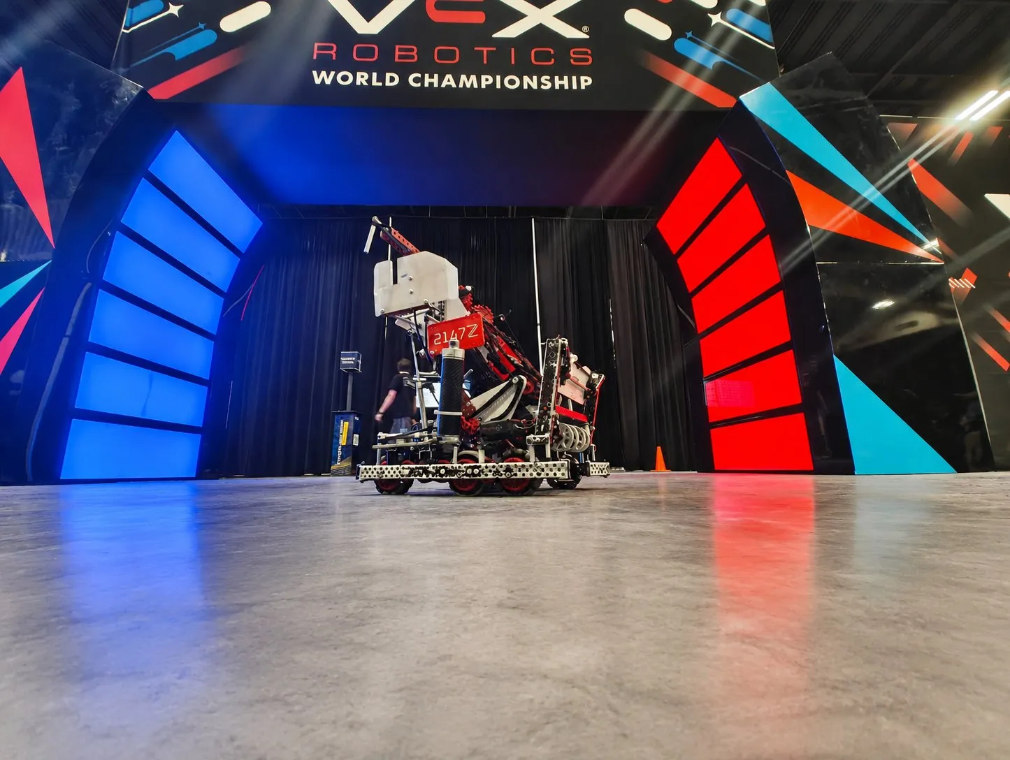
- Team
- VEX Team 2147Z
- Role
- Design and programming lead
- Period
- Oct 2025 to Apr 2026
- Drive
- 6 × 11 W motors, 450 rpm
- Lift
- Two-bar, 2 × 75 mm pneumatic pistons
- Fabrication
- Laser-cut polycarbonate
- Code
- C++ on PROS
Starting over
We began the season with a hopper-style robot. After a few competitions it was clear that it was far too inefficient to keep up with the strategies other teams were running, so we dropped it and designed our first basket-style robot with a three-stage intake.
Chassis
I designed the chassis around the obstacles on the field, aiming for strength, agility, and speed. The drivetrain is six 11 W motors on 600 rpm planetary gearboxes, geared down 4:3 to 450 rpm at six drive wheels. The rear of the frame funnels through a 1/16 in polycarbonate drive cap, laser cut. The frame is 0.500 in × 1.000 in × 0.500 in aluminum C-channel, with 0.250 in × 0.375 in L-channel on the lift to save weight.
Laying out the whole drivetrain in CAD cut production time and made sure it would work with the subsystems that came after it.
Lift and intake
The robot has to fit under the long goals on each side of the field, so the lift is a two-bar that squats down to center-goal height. The usual way to hold a lift up is with elastics, but the bands had no clear place to mount. A polycarbonate spring pushes the intake up instead, and two 75 mm pneumatic pistons pull the lift down. That kept the footprint small and the air use low.
I chose the intake and lift designs with a decision matrix, and made the whole intake out of custom polycarbonate to keep the lift light. I set the intake ramp and sprocket angles from a 2D sketch of the ball path and placed the pistons with Inventor motion studies.
Checking and cutting the parts
I ran FEA in Inventor to check that two polycarbonate parts stay rigid: the front drive endcaps, which take hits when we play defense, and the top intake plate, the most critical piece of the intake. Modeling the parts with the Inventor Sheet Metal tools kept the bends in the model. The bent parts were flattened into cut files, which I nested in Deepnest so they use as little sheet as possible, and then we laser cut them.
Control software
The code is C++ on PROS, a real-time operating system for the V5 brain, on top of the LemLib library. Each subsystem is its own class, so the code can change as the robot does.
A PID controller corrects an error three ways: in proportion to the error now, to its running total, and to how fast it is changing. The proportional term does most of the work, the integral term removes the small offset that is left over, and the derivative term damps the approach so the mechanism settles instead of ringing. The integral is zeroed when the error changes sign or is outside a windup range, so it cannot build up while the mechanism is far from its target.
// calculate integral
integral += error;
if (sgn(error) != sgn((prevError)) && signFlipReset) integral = 0;
if (fabs(error) > windupRange && windupRange != 0) integral = 0;

// calculate derivative
const float derivative = error - prevError;
prevError = error;

// calculate output
return error * kP + integral * kI + derivative * kD;Odometry
Odometry tracks where the robot is on the field using two tracking wheels mounted perpendicular to each other and the heading from the inertial sensor. Every loop it reads how far each wheel has turned since the last update, rotates that local movement by the average heading over the update, and adds the result to the global X and Y position.
// calculate local x and y
float localX = 0;
float localY = 0;
if (deltaHeading == 0) { // prevent divide by 0
    localX = deltaX;
    localY = deltaY;
} else {
    localX = 2 * sin(deltaHeading / 2) * (deltaX / deltaHeading + horizontalOffset);
    localY = 2 * sin(deltaHeading / 2) * (deltaY / deltaHeading + verticalOffset);
}

// calculate global x and y
odomPose.x += localY * sin(avgHeading);
odomPose.y += localY * cos(avgHeading);
odomPose.x += localX * -cos(avgHeading);
odomPose.y += localX * sin(avgHeading);
odomPose.theta = heading;Intake state machine
A state machine holds a subsystem in exactly one of several named states, with rules for moving between them. The intake cycles through Brake, Intaking, Center, High, Outtaking, and Matchloading, and each state sets which motors run and how fast. Driver control and autonomous code share one interface into the intake, so a change to one state applies everywhere that state is used. A background task on a 20 ms loop runs the anti-jam check, color sort, and piston safety before it writes the motor voltages and piston states.
The robot running
Recorded runs from the shop and from the April 2026 competition.
Result
The team went to the VEX World Championship representing Southern California and finished in the top 8% of all teams there. We ranked #33 in the world in programming skills. We also won 6 awards during the season, including the Build Award at the California Region 4 championship, which qualified us for Worlds.
